This is a write up of a hack to replace the 4 2516 game EPROMs with a single 2764 EPROM, this hack is designed in a way that makes no permanent modifications to your game board. The only alterations to your game board is soldering 2 wires to unused edge connector test points, these can be desoldered in less than a minute without any damage to the board.
| What you will need for this hack |
- 1 2764 or 2564 EPROM chip
- 2 1/4 quick disconnects
- about 3 feet of 18 or 20 gauge hook up wire
- 2 28 pin (.6") IC sockets
- a solder iron and solder
- a wire stripper and crimp tool
- A EPROM programmer (or someone to program your 2764 EPROM)
|
| The image below shows the pinouts and the numbering of the 2764 chip (and socket). In the instructions below we will refer to the pin number shown in the diagram |  |
|
Remove the 4 2516 EPROMS from your game board (In slots ROM 0, ROM 1, ROM 2, ROM 3)
|
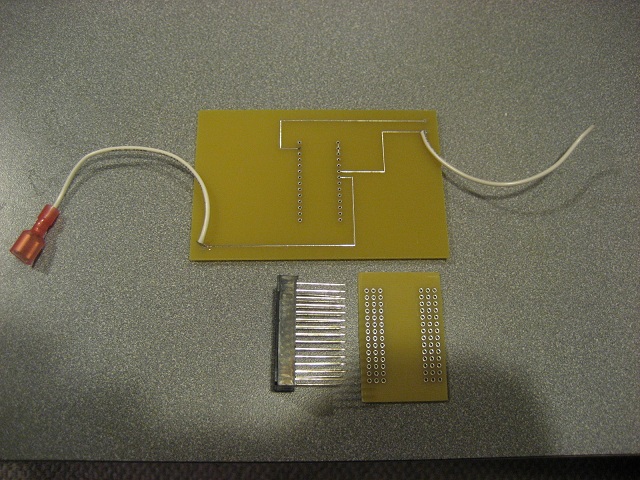
- Get 2 empty 28 pin (.600) sockets.
|
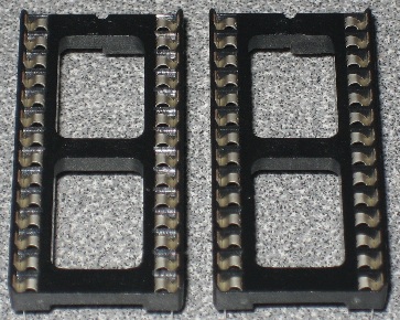 |
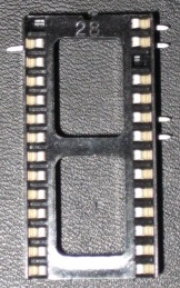
| On one of the empty sockets, remove the metal contacts from position 1,2,26,27,28 | 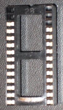
|
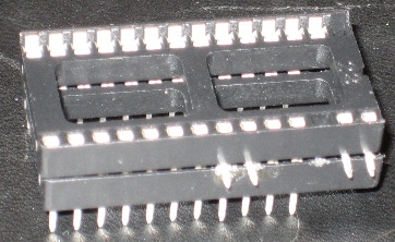
On the other empty socket
- Remove the metal contacts from position 1 and 26
- At the bottom bend back the metal pins 90 degrees on position 2, 22, 23, 27 and 28
|
|
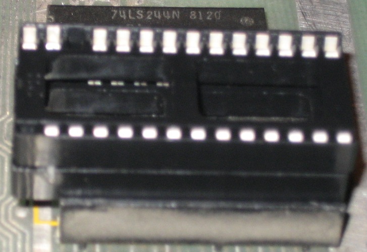
- Insert the socket you modified in step 3, into the socket you modified in step 2
|
 |
- Insert the new set of sockets into any of the free ROM slots (ROM 0,1,2 or 3) on your Centipede PCB board.
- Ensure that the back of the new socket stack are aligned with the back of the original ROM socket. The front two pins on each side of the new rom sockets should be hanging over the front of the old socket
|
 |
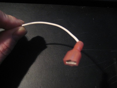
- Cut 2 lengths of wire, one about 4 inches, the other about 20 inches
- Terminate one end of each wire with a 1/4 quick disconnect
|
 |
- solder the free end of the 4" wire to pin 22 on your socket stack
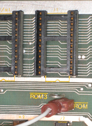
- plug the quick disconnect into the test point labeled "ROM" (with a line above it) underneath the empty ROM3 slot on your centipede PCB
|
 |
- solder the free end of the 20" wire across pins 27 and 28 on your socket stack
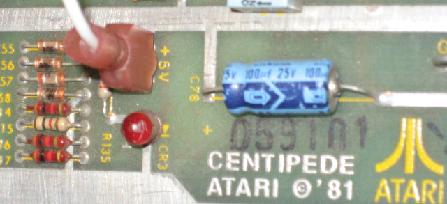
- plug the quick disconnect end into the +5V test point all way on the other end of the centipede PCB (near the edge connector and Atari logo)
|
 |
- Cut 2 lengths of wire each about 6"
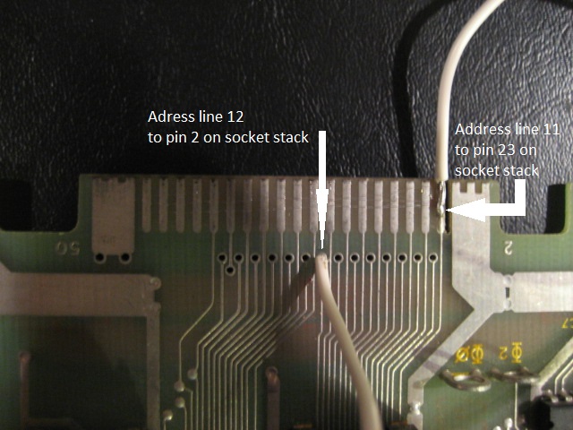
- Take one end of the wire and solder it to pin 23 on your socket stack, solder the other end of the wire into the address line 11 edge connector test point on your centipede board
- Take the other wire, solder one end to pin 2 on your socket stack, solder the other end to address line 12 edge connector test point on your centipede board
|
 |
- program your 2574 EPROM with the centipede single rom image provided
|
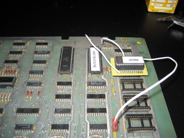
- Insert your EPROM chip into the socket stack, and your good to go!
|
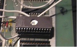 |
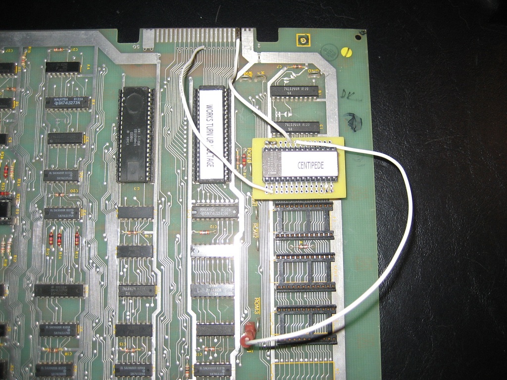
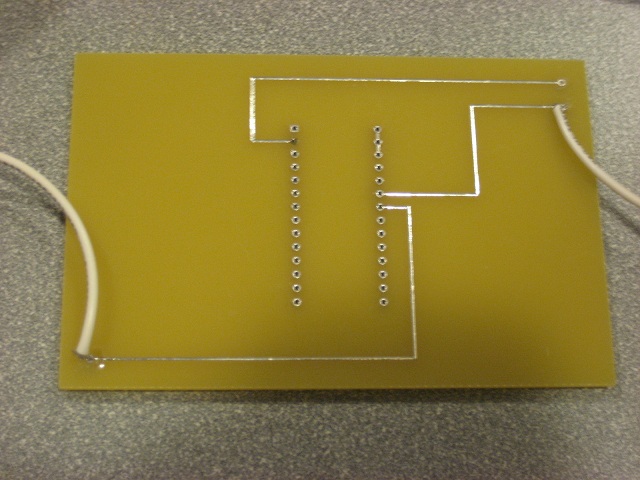
The finished hack (shown with arcadeshop.com's centipede to JAMMA adaptor board attached)
Both the boards above avoid the long +5V wire. On the original socket for the 2517 pin 24 is +5V, that associates to pin 26 on our 2764. But on the 2764, pin 26 is not actually connected at all to the chip. So we can simply run a trace from pin 26 to 27 to 28 on our new socket to distribute +5V to both the points we need it to go.
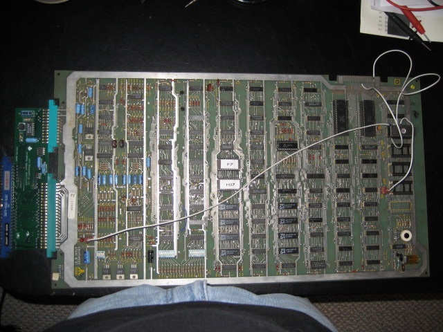
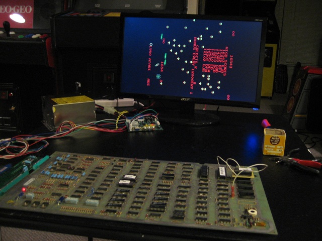
Below are picture of the game with the single rom hack and plug and play board installed.