carnival troubleshooting information

Copyright 2015 Brian Brzezicki
version 1.01 3/22/2005
version 1.10 3/22/2005 - added information on sounds and music

This was started as a troubleshooting guide for Carnival, however most of this information besides the ROM signatures should apply to any of the Sega VIC/VIC dual based games.

Information on Carnival RAM

Important, Carnival REQUIRES MK4027 or MK4015 RAM, other dynamic RAMs with the same pinout (such as 4164) will NOT work

RAM range 0x8000 - 0x8FFF
Each RAM chip holds 1 bit of the each address

Chip locationBit
U76Bit 0
U75Bit 1
U74Bit 2
U73Bit 3
U72Bit 4
U71Bit 5
U70Bit 6
U69Bit 7

Information on Carnival ROMs

The carnival ROM ranges are 0x0000 - 0x3FFF
If you have a Fluke 9010a the easiest way to test them is to test them all at once, since likey they will be good

RangeFluke ChecksumROM location
0x0000 - 0x3FFF271aAll ROMS (u31-u26, u7-u1)

RangeFluke ChecksumROM location
0x0000 - 0x1FFF73e0Top Row (u33-u26)
0x0000 - 0x03FF9359u33
0x0400 - 0x07FF859bu32
0x0800 - 0x0BFFc101u31
0x0C00 - 0x0FFF26bfu30
0x1000 - 0x13FF2b81u29
0x1400 - 0x17FFb7e8u28
0x1800 - 0x1BFFa5f0u27
0x1C00 - 0x1FFF05d9u26

RangeFluke ChecksumROM location
0x2000 - 0x3FFFe212Buttom Row (u7-u1)
0x2000 - 0x23FFa4deu8
0x2400 - 0x27FFa3feu7
0x2800 - 0x2BFF8909u6
0x2C00 - 0x2FFFccdbu5
0x3000 - 0x33FFf52du4
0x3400 - 0x37FF29b6u3
0x3800 - 0x3BFF3fd8u2
0x3C00 - 0x3FFFe09fu1

miscellaneous signals

U57 is a 40 pin custom chip that handles RAM addressing, as well as video timing. Here are a list of pins and signals to expect
PinSignal
13 (Input)645Khz
14 (Input)1.93Mhz
23 (Input)5.15Mhz
29 (Input)645Khz
30 (Input)1.93Mhz
15 (Output)15.7Mhz (not exact, it's a composite sync signal, so it mostly looks like a 15.Khz signal, with the verticl component also included)

Signal output from U19

pinSignal Frequency
25.15Mhz
6645 Khz
10645 Khz (inverted in respect to pin #6 signal
151.93Mhz

Signal output from U20

pinSignal Frequency
2645Khz
7645 Khz
101.93Mhz
141.93Mhz
151.93Mhz

Trouble shooting the coin up circuit

Sega VIC games do not coin up like normal games which is usually just groudning some pin. The coin up circuit actually resets the CPU and sends a signal. Whats more you cannot just ground a pin, you actually need to ground one pin and set another high at the same time. I will attmempt to provide a troubleshooting flowchart for troubleshooting the coin up circuit on Sega/Gremlin VIC/Dual VIC games.

Perform the following steps/tests in ORDER, do NOT skip, each step is a prerequite to the next. If one of the steps fixes the problem, then stop.


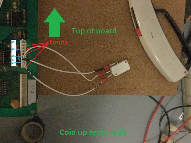
  1. Build this coin up test harness, as shown in picture below
  2. Unplug the coin meter from the PCB board
  3. Unplug the photo coin calculators from the PCB board
  4. Plug in your test circuit, pin #1 on the test harness to pin #11 on the PCB board, pin #9 on the test harness to pin #18 on the PCB board, as shown in the picture above.
  5. Setup a logic Probe (a voltimeter should work OK) and a ohmeter
  6. Check continuity between pin #15 on the PCB header and pin #4 @ U62 (74LS00), find break if continuity is bad (it should be about 330 Ohms)(only component between is R31)
  7. Check continuity between pin #17 on the PCB header and pin #10 @ U62 (74LS00), find break if continuity is bad (it should be about 330 Ohms) (only component between is R32)
  8. Turn on the game
  9. set logic probe on pin #6 of U62, hit the button on the test harness, ensure the logic probe changes states when you press the microswitch contact, if not replace U62
  10. set logic probe on pin #8 of U62, hit the button on the test harness, ensure the logic probe changes states when you press the microswitch contact, if not replace U62
  11. Turn off the game
  12. with multimeter check continuity between pin #6 on U62 and the base (B) of Q4, resistance should be about 1K Ohms, if not replace R11 or find the break in the trace and repair.
  13. Turn on the game
  14. place your logic probe on the Collector (C) of the 2N4401 @ Q4, it should be high, press the button on the microswitch, it should go low, if not replace Q4
  15. place your logic probe on the Emmiter of (E) if the PE8050 @ Q3, it should be high, press the button on the microswitch, it should transistion low, if not replace Q3
  16. Place your logic probe on pin #2 of 74LS08 @ U35, it should be high. Prese the button on the microswitch it should go go low then back high, if not verify that R8 (470 ohm resitor), D3 (IN914 diode), C29 (.1uf cermamic capacitor) , D4 (IN4002) and R10 (10000 ohm resistor) are OK.
  17. Place your logic probe on pin #3 of 74LS08 @ U35, it should be high. Prese the button on the microswitch it should go go low then back high, if not replace U35.
  18. Turn off game
  19. Test continuity from pin #8 of U62 to pin #11 of U43, if no continuity find and replace break in trace
  20. Test continuity from pin #8 of U43 to pin #13 of U253, if no continuity find and replace break in trace
  21. Turn game back on
  22. place logic probe on pins #8 of 74LS74 @ U43, then test pin #9, make sure they are the opposite of each other, if not replace U43
  23. If everything is OK to this point and the game boots up to the attract mode, replace U24 (74LS02)
  24. if that did not changes anything replace U45 (74LS253)

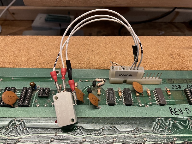
    If you are using a VIC 1 board (like Head On) setup the connector as shown in this picture
    Information on Sounds

    The sounds in carnival are triggered by writting certain bits to an IO address. The data is read directly off the data bus by 2 74LS374 flip flops at U63 and u64. For the sounds in the table below you can test the sound by manually grounding the respective pin. Here is the information
    PCB header pinSoundChip U63 or U64Pin on chipI/O addressBit position (0-7)
    29 Bonus #2 U64 12 7
    30 Bonus #1 U64 9 6
    31 Pipe U64 15 5
    32 Duck #3 U64 6 4
    33 Duck #1 U64 5 2
    34 Duck #2 U64 16 3
    35 Clang U64 19 1
    36 Rifle U64 2 0
    43 Ranking U63 15 5
    45 Bear U63 5 2
    Main PCB header pins 41,42,47 and 48 are unused

    Carnival, Main PCB to Music Board

    PCB header pinSoundChip U63 or U64Pin on chipI/O addressBit position (0-7)
    44 ??? to Music Board U63 6 4
    46 ??? to Music Board U63 16 3

    Main PCB header pins 49-52 are to provide power to the sub boards.
    PCB header pinVoltage
    49 +12
    50 -12
    51 Ground
    52 +5

    0xc000 - 0xc37F - tiles
    0x93:0 -> 0x9c: 9

    Tiles (bottom left = 0x00, moving up and over to the right)
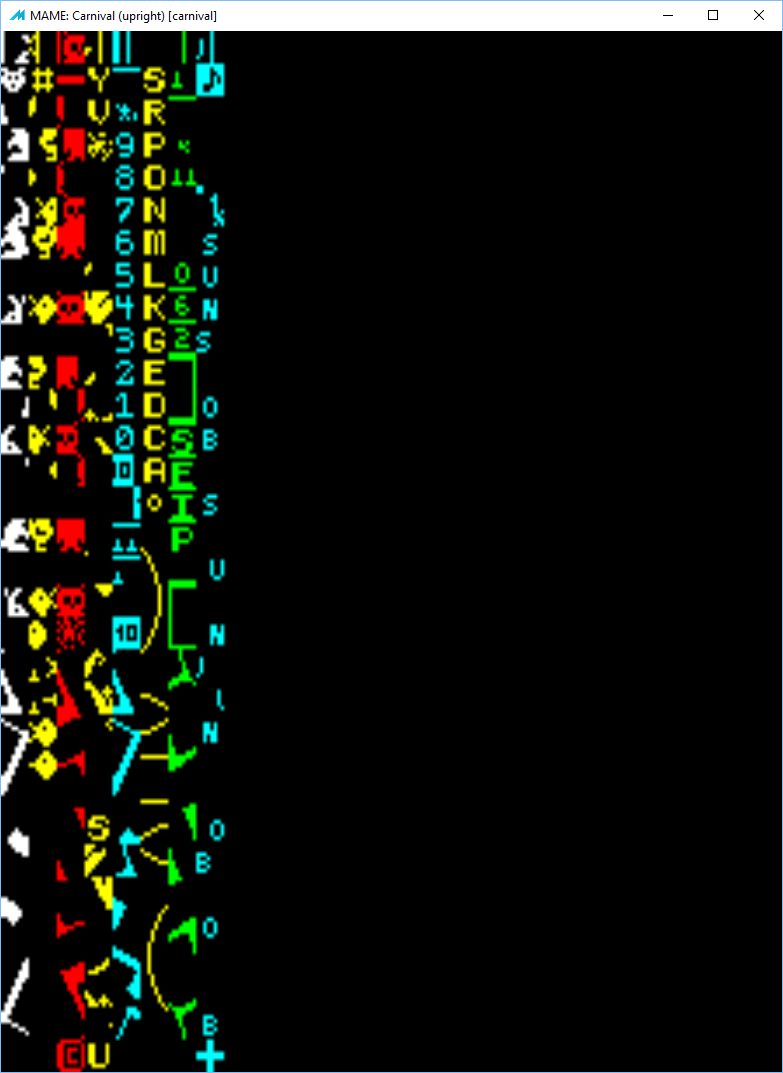
    Note: pulsar has the entire alphabet at it's ASCII values (0x41 = A - Z), and 0-9 at (0x30 - 0x39)

    Important Note: The carnival hardware has ROM from 0x0000 - 0x3FFF HOWEVER it is mirrored into 0x4000 - 0x7FFF and this mirror MUST exist! The code calls routines in this upper address space (0x4000 etc) so if it's not mirrored things don't work!

    RAM is also from 0x8000 - 0x8FFF but the hardware maps this into each areas (0x9000 - 0x9FFF, 0xa000 - 0xaFFF... 0xf000 - 0xffff) but the range at least in carnival uses 0xe000 - 0xefff

    Schematics for Dual Vic board