This is a write up of a hack to replace the 4 2516 game EPROMs with a single 2764 EPROM, this hack is designed in a way that makes use of the extra un-populated ROM socket on the centipede board. By hacking this unused ROM socket you can switch between the single ROM version or the regular version without having to "un-hack" the board.
| What you will need for this hack |
- 1 2764 EPROM chip
- about 6 inches of high gauge (thin) jumper wire
- 1 24 pin (.6") IC sockets
- 1 28 pin (.6") IC sockets
- a solder iron and solder
- a solder sucker
- a wire stripper and crimp tool
- A EPROM programmer (or someone to program your 2764 EPROM)
- A Centipede version -01 PCB board
|
| The image below shows the pinouts and the numbering of the 2764 chip (and socket). In the instructions below we will refer to the pin number shown in the diagram |  |
|
Remove the 4 2516 EPROMS from your game board (In slots ROM 0, ROM 1, ROM 2, ROM 3)
|
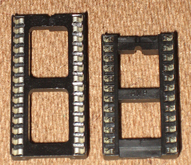
- Get 1 empty 24 pin (.600) sockets.
- Get 1 empty 28 pin (.600) sockets.
|
 |
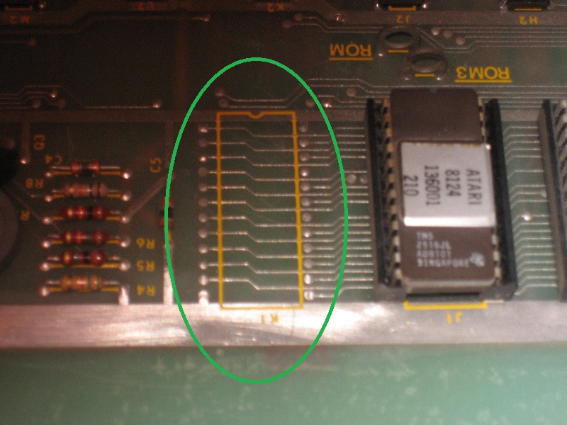
- Notice that the centipede board has an un-populated socket area at position K1
|
 |
- De-solder the socket via's and solder in a 24 pin socket
|
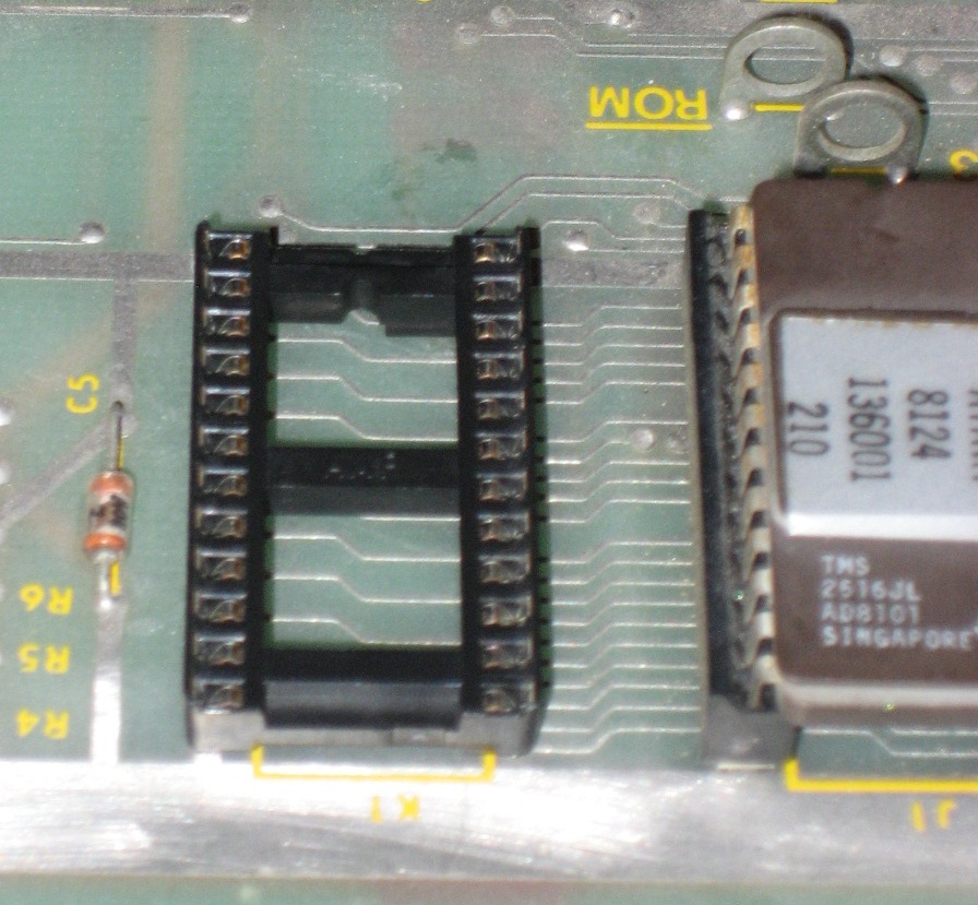 |
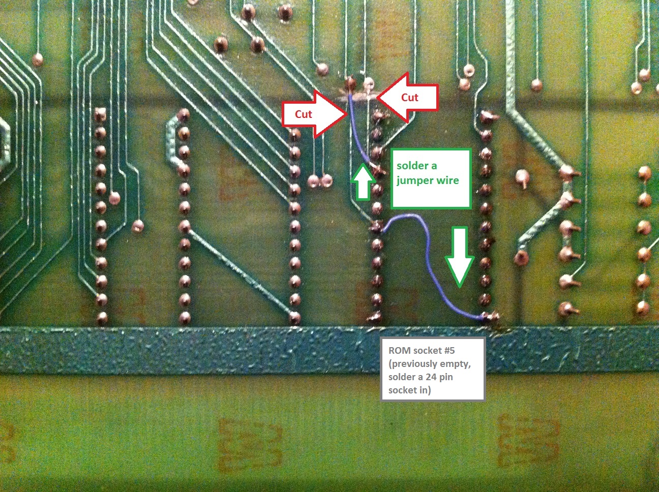
- Flip the board over
- Cut the 2 traces in the PCB as shown
- Solder in the 2 jumpers wires as shown
|
 |
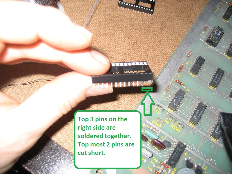
- Flip the board over
- Take the 28 pin socket, solder together (use some jumper wires) the top 3 pins on the right side (pin 26,27, 28)
- Cut off the as much of the top right 2 pins (27,28) as possible
|
 |
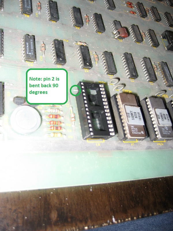
- On the left side of the 28 pin socket, cut off pin 1, and bend pin 2 out at a 90 degree angle
- Insert the 28 pin socket into the 24 pin socket at K1,ensuring that the backs of both 24 and 28 pin sockets are flush. The first 2 rows of the 28 pin shocket should be haning over the front of the 24 pin socket
|
 |
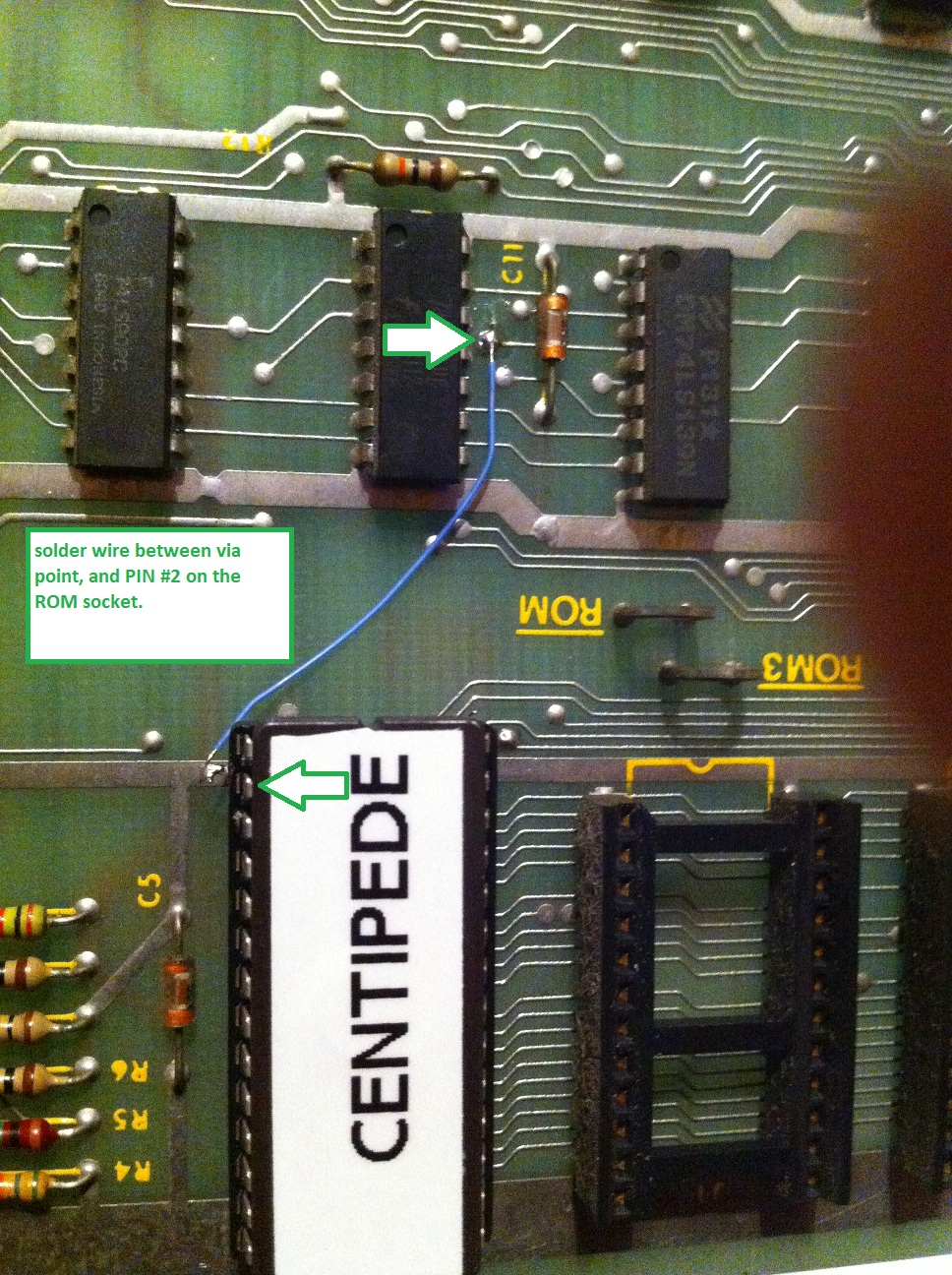
- Solder a wire trace to the bent back pin (pin 2) and the via shown in the picture
|
 |
- program your 2764 EPROM with the centipede single rom image provided
- Insert into the 28 pin socket as shown above
|
7/29/2014 - A plug and play replacement! available from